Maytronics Rev 03 board partial power schematic
by Steve Hobrecht
(Northern California)
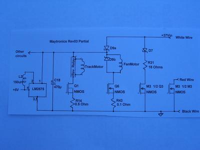

This is an updated and correct schematic of the Dolphin Diagnostic built in 2006 using their Rev 03 Motor control circuit board. The track motor relay is hooked up to reverse the motor connections when energized. The LM2575 is used to generate the +5V supply used by all of the logic circuitry, including the Atmel Mega16 microcontroller. The red wire is hooked up to the PC board but is not wired up when it gets into the Land power supply plug. The resistors seem underrated based upon the feedback of problems from the field and/or increased motor load currents over the operating life of the unit. It does appear that the motor control board is protected from power reversal of the input power lines but the controller will not operate under these conditions.
Comments for Maytronics Rev 03 board partial power schematic
|
||
|
||
