Resistor Value for R43

by Gibson
(Sacramento, CA)


Hello!

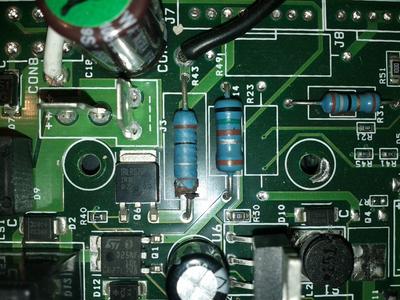
I am trying to find out the resistance value, tolerance, and wattage for the resistor labeled R43 (in the box labeled J3) for the Dolphin 2410012LF Rev 04 circuit board. It is located next to the BLACK soldered wire on the board. Mine is burnt out and I can't read the color bands (color blind) or ohm test it. Any help would be GREATLY appreciated!!

Thank You,
Gibson Howell
916/730-0141

Comments for Resistor Value for R43

Average Rating starstarstarstarstar

Click here to add your own comments

Aug 15, 2022
Rating
starstarstarstarstar
R43 value
by: Anonymous

The values and recommended wattage for the resistors is:

R14 0.5 Ohm 3 Watt

R31 18 Ohm 3 Watt

R43 0.1 Ohm 3 Watt

Aug 15, 2022
Rating
starstarstarstarstar
D9 componentt burn
by: Anonymous

HELLO,


What is the spécification of D9 components, mine is burn

May 28, 2020
Rating
starstarstarstarstar
Composant s1
by: Gaby

Bonjour, ou puis-je trouver le composant s1 de la carte maytronics 2410012lf de mon robot piscine.
Ou existe t il un moyen de le supprimer ou autre ?
Merci

Jul 26, 2018
Rating
starstarstarstarstar
Motor current
by: Thehobe

The low valued resistors are used to sense the currents in the motors. The software written into the microcontroller has the ability to shut down the robots operation if the motor current is not in the proper range, either too little or too much current. I assume the current is too low in the top motor (fan) if the robot is out of the water because there is no water resistance to load the motor. I do not know if running the robot out of the water permanently ruins the robot or it just stops, knowing that the motor currents are not correct. The rear bearings on the internal motors are set in plastic shells and have been seen to overheat, crack, and destroy themselves.

Jul 26, 2018
Rating
starstarstarstarstar
CONFUSED ABOUT R 43 (the whole message)
by: VIRGYL TRACEY

Hello again
Can anyone help please? I still haven’t understood: The R 43 protects the turbine motor? (Mr. MCJ wrote: <>. Also Mr. Steve Hobrecht wrote: <>) Or the crawlers motor? (Mr. TheHobe wrote: << … a rag got caught in my rolling brush, jammed the motor and burned out my resistor…>>) Yours truly

Jun 29, 2018
Rating
starstarstarstarstar
S1 identity
by: Thehobe

S1 appears to be a photodiode and phototransistor pair that may be being used for electrical isolation. You can remove part of the plastic cover to see the components mounted inside.

Jun 29, 2018
Rating
starstarstarstarstar
U1
by: Anonymous

U1, on my board is a hex schmitt trigger IC: M74HC14.

Jun 29, 2018
Rating
starstarstarstarstar
U1
by: Anonymous

Hello to all,
Can someone tell me label of U1 chip (is fried)?

May 03, 2018
Rating
starstarstarstarstar
Another Component
by: Stefan

Can someone tell me what that component is?
On the board labeled S1
Thanks Stefan

Mar 31, 2018
Rating
starstarstarstarstar
R43 burned out
by: thehobe

You can buy the resistor from China on Ebay for a couple of $ for 10 of them but again, the problem is either cracked robot case, dried out bearings, and or failed plastic motor endcaps holding the overheated bearings and cracking. A rag got caught in my rolling brush, jammed the motor and burned out my resistor and also appears to have caused a crack in the Dolphin case resulting in a case water leak as well.

Mar 31, 2018
Rating
starstarstarstarstar
R43
by: Anonymous

Excuse me the R43 is 0.1 Ohm and 3 Watts.

Mar 31, 2018
Rating
starstarstarstarstar
R43 burnout, value and reason why.
by: Anonymous

As I stated years ago, it is a 1 ohm 3 Watt resistor. The most likely cause of this resistor burning out is the increased motor current as the bearing holders at each end of the motor start to melt due to friction and "lifetime" lubrication.

Mar 30, 2018
Rating
starstarstarstarstar
Fixed it
by: MCJ

I now know the problem you all had and it's not electronic. The seal on the motor shaft of the turbine is not lubbed enought anymore, which causes friction on serious increase on the current draw. This is what may frie the sensing resistor (0.5ohm by the way)and/or is detected by the uprocessor which the stops the robot.

Note : The grease must be replaced by high quality grease, I used high pressure lithium grease. I tried a cheap grease first but that didnt fix the problem.

MCJ (electronics engineer)

Aug 22, 2016
Rating
starstarstarstarstar
No boards available from the factory
by: thehobe

There are no boards available from the factory probably because the boards are not the cause of most failures. The boards go bad after the motors draw excessive current. When the motors draw too much current the current sensing resistors fail due to excess thermal stress.If something gets caught in the wheel while the robot is running, the motors can draw excessive current and also burn out the sensing resistors. Your motors, even though they seem to run OK, are probably drawing too much current. The internal intelligence of the control board will halt the robot operation under excessive current conditions, but this may be too late for those resistors, especially in a stall situation.

Aug 22, 2016
Rating
starstarstarstarstar
buy new motor board
by: Anonymous

does anyone know where i can buy a new board for the motor? I have 2 motors both with bad boards

does anyone sell or fix the boards?

Aug 18, 2016
Rating
starstarstarstarstar
The value of R43 is:
by: thehobe

The values and recommended wattage for the resistors is:

R14 0.5 Ohm 3 Watt

R31 18 Ohm 3 Watt

R43 0.1 Ohm 3 Watt


Aug 18, 2016
Rating
starstarstarstarstar
R14 fried
by: Finn

Hi - My problem on the 2410012LF board is, that the R14 is fried. From pictures in this thread it look like the resistor is black green brown silver brown. Is that correct ? How many ohm is that ? (strange, that first ring is black)
I havre found pictures of the board, where the R14 resistor is shunted with another resistor (yellow purple gold gold=4,7ohm ?)- why is that?
I don't know, where R14 connect to.

Jul 06, 2016
Rating
starstarstarstarstar
R43 0.1 Ohm 3 Watt
by: thehobe

If R43 is open, one of the motors will not start.

Jun 22, 2016
Rating
starstarstarstarstar
Resistor Value for R43
by: Francisco Ventura

could someone help me, and let me know the correct value for R43
Pictures
http://www.cjoint.com/c/FFwjBPrQHPm
http://www.cjoint.com/c/FFwjJokXTam
http://www.cjoint.com/c/FFwjKVjoofm
http://www.cjoint.com/c/FFwjMH5sJnm

Jun 22, 2016
Rating
starstarstarstarstar
MAYTRONICS ORION REV02 2410011LF
by: Francisco Ventura

MAYTRONICS ORION REV02 2410011LF


Hi i have the same problem, resistor R43 is fried.
i dont know the color code, in order to buy a new one.

could someone help me, and let me know the correct value for R43


Pictures

http://www.cjoint.com/c/FFwjBPrQHPm
http://www.cjoint.com/c/FFwjJokXTam
http://www.cjoint.com/c/FFwjKVjoofm
http://www.cjoint.com/c/FFwjMH5sJnm

Jun 22, 2016
Rating
starstarstarstarstar
Resistor Value For R43
by: Francisco Ventura

Hi i have the same problem, resistor R43 is fried.
i dont know the color code, in order to buy a new one.

could someone help me, and let me know the correct value for R43


Jun 22, 2016
Rating
starstarstarstarstar
Resistor Value For R$·
by: Francisco Ventura

Hi i have the same problem, resistor R43 is fried.
i dont know the color code, in order to buy a new one.

could someone help me, and let me know the correct value for R43


Apr 24, 2016
Rating
starstarstarstarstar
Resistor
by: Anonymous

Please send me the data from the resistor R43

Oct 11, 2014
Rating
starstarstarstarstar
Little green light
by: Thehobe

Yes, the led is part of the microcontroller system that shows that it is operating. Mine blinks as long as power is applied. The rate at which the LED blinks is about once per second. It continues to blink even after all motors are stopped.

Oct 10, 2014
Rating
starstarstarstarstar
2410012LF
by: Ed

TheHobe:
Does the little green led blink on your board? That is the only activity I am seeing now.

I don't seen any attempt to move the motors at startup, but will check further to see if the Atmel controller is doing something at startup.


Oct 10, 2014
Rating
starstarstarstarstar
PWM drive
by: Thehobe

The DMOS devices are driven with a Pulse Width Modulated signal kind of like a switching regulator works. The motor acts a "filter" to the driving square wave signal just like the speaker amplifier does in type "D" digital drive.

Are you familiar with switching regulator drive circuits?

Are you using an oscilloscope to measure the "0V" signals?

If your Dolphin did the normal "a little forward...and a little back" then the motor and driving circuits are working and the microcontroller is trying to be intelligent and turning off the Dolphin motors.

Oct 10, 2014
Rating
starstarstarstarstar
Correct partial schematic
by: Thehobe

See link:
https://www.i-love-my-aquabot-automatic-pool-cleaner.com/dyn/C2/SubmitInvitation

If the DMOS devices are not getting turned on, the logic chip driving their gates would be the next culprit although I would not suspect a problem there.

Your issue may go back to the Atmel ucontroller itself for not sequencing either of the DMOS switched.

There could also be a subroutine in the ucontrooler that has not even attempted to turn the devices on.

You need to keep going back in the circuit until you find the problem.

With most failures I see, both motors normally turn on for an instant and them the ucontroller shuts down the system.

Oct 10, 2014
Rating
starstarstarstarstar
2410012LF Rev 3
by: Rf

The debug continues. I've checked the two motors and they work (with voltage applied directly to them when disconnected from the board).

When connected to the circuit board, the motors get no current, however. Neither Q1 (track motor driver) nor Q6 (pump motor driver) are enabled to activate the motors.

Q1 and Q6 should be turned on by the 7402 (U7 pin 1 for Q6 and U7 pin 13 for Q1). These pins both sit at 0 volts. U7 has 5v power, which indicates that the voltage regulator U6 is working.

My only other clues are that the motor connectors J3 and J4 have +28volts on the +++ pins, and the little green LED D4 blinks about one per second.

So what could be preventing things from working?

Is there some startup sequence that I don't understand. I think I have everything connected as it should be.

I still don't know what the red wire to the board does (the white and black wires supply 28 volts).
The red wire does not appear to be connected to anything off the board except an unused pin on a connector.

Any help would be appreciated.

Thanks,
Ed

Oct 08, 2014
Rating
starstarstarstarstar
Schematic
by: Thehobe

Ed, See my post.
https://www.i-love-my-aquabot-automatic-pool-cleaner.com/maytronics-rev-03-board-partial-schematic.html
Partial schematic.

Oct 08, 2014
Rating
starstarstarstarstar
Dolphin 2410012LF rev 03 photo
by: Ed

I found a link to a good photo of the board:

http://cjoint.com/13sp/CIkvF3Amx7T_2410012.jpg

Oct 08, 2014
Rating
starstarstarstarstar
R31 restor value?
by: Ed

I agree that a small resistance would be more logical here. Maybe someone has a 'good' resistor on a board and could measure the resistance? It might require lifting one end to be accurately measured.

Oct 08, 2014
Rating
starstarstarstarstar
R31
by: Thehobe

The picture looks like the value IS 19 Ohms but this is a non-standard value that makes me suspicious. The photo looks like brown (1), white(9) black (0), gold (x.01). but I wasn't sure. When the M3 DMOS fet turns on, the current drawn would be about 1.5 Amps because the supply sags to around 30V. This may be being used as a calibrator for the main power supply and not a "resettable fuse" as I have alluded to in the past....unless all motor are turned on as well at the same time. The other issue is that it appears to be about a 2W resistor and cannot take the 1.5 Amp current for very long! That's about 70 Watts(1.5x1.5x30V= 67.5W). This path is not being turned on for long or it is an indicator to the field service repair centers when they see a burned out resistor!

Oct 08, 2014
Rating
starstarstarstarstar
2410012LF voltage in question
by: Ed

I need help. My circuit board has a white wire soldered to CON8, which is near diode D7 and near the big spade connectors to the track motor.

I cannot determine what on the board is connected to CON8. Can someone tell me what CON8 is supposed to connect to?

I'm suspecting that it might be one side of D7, but don't know. Can someone with a board handy check with an ohmmeter what the white wire to CON8 is electrically connected to on the board?

Thanks very much!
Ed


Oct 08, 2014
Rating
starstarstarstarstar
R31
by: Thehobe

The pinit picture at the top of this post I thought was your board. R31 looks intact unless this is not your board or you ran the Dolphin out of the water and burned it up like I did! Is that your board in the picture?

Oct 08, 2014
Rating
starstarstarstarstar
R31 value
by: Ed

I'm sorry, but the R31 that was on my board was burned/corroided beyond recognition. So I could not determine its resistance.

I found (somewhere on this forum) that R31 should be 19 ohms. I'll look further and see what I can find.

A schematic of this board would be great to have!

Oct 08, 2014
Rating
starstarstarstarstar
R31 value for many others
by: Anonymous

Ed, now I have a question for you. I need to know the value of your R31 but I am not sure of the color of the second band in your picture. It is either brown green silver or brown white silver but I cannot quite make it out.
Your board appears to be in quite undamaged condition and MAY only need R43 for repair as well as sealing of the motor case from future motor leaks. I have ordered some R43 valued resistors but it will take several weeks for them to arrive. They are the same type that Maytronics uses in their rev 03 boards.
If you can measure R31 with an ohmmeter that would be great but it is probably too low a value to measure on a typical ohmmeter.

Oct 08, 2014
Rating
starstarstarstarstar
PC board continuity
by: Thehobe

I would not even attempt to repair a board if this kind of damage is actually there! I seriously doubt that your PC board inner layers are compromised this badly. This appears to be a 4 layer board and this is why it is hard to measure and guess just how it is hooked up without some significant circuit experience behind you. I have 35 years in the Analog Design field and it is still difficult to figure out exactly how the board is wired up without spending a lot of time on it. I have powered the board on the bench with a bench power supply and have watched with an oscilloscope how the motors are slowly turned on with the PWM driving approach. On the bench, without the proper loading on the motors(i.e. pump water drag and track motor loading), the Atmel program turns off the motor drives after 20 seconds to maybe a minute depending upon how I physically load the motors. You will need to learn C++ programing and many power electronic design aspects in order to repair or design a PC board for this application.

Oct 07, 2014
Rating
starstarstarstarstar
2410012LF
by: Ed

Thanks, Thehobe, for that information.

My circuit board show conductivity from the anode of D7 (pin near D9) to one of the outside pins of D9. However, there is no conductivity to the white wire connection marked CON8.

Should these points be connected? If so, do you think that my board might have an open circuit inside?

I can connect these points, but don't want to take a chance and blow something up!

Thanks again,
Ed

Oct 07, 2014
Rating
starstarstarstarstar
R43
by: Thehobe

It is most definitely not 18 ohms but 0.1 Ohm and I have measured it.

The red wire coming into my unit hooks up at the PC board side but not in the power supply unit. It is tied to the drain of one of the dual DMOS FETs in package labeled Q3.

The motors are driven with a pulse width modulated signal generated by the program code of the Atmel microcontroller.

The Vin line is connected to the electronics on the board through D7 and half of double diode D9. The other half od D9 acts as a recirculation diode for the pump motor each cycle the PWM drive turns off (or just a pass diode). The capacitor is most likely connected to the low side of all of these circuit reverse protection diodes.

The circuit design is a modern, fairly smart electronic motor driving unit, allowing the track motor to reverse using the DPDT relay and PWM motor speed control. This is not a trivia motor on/off type of unit so redesign involves a lot of careful work.

Also, my unit has stress cracks around the track drive motor shaft, very fine cracks letting in water slowly.


Oct 06, 2014
Rating
starstarstarstarstar
2410012LF
by: Ed

Another question please: How is the positive power routed on the board? Mine doesn't seem to go anywhere from where the wire is soldered on the board. I was thinking that it might go to the + terminal of C18, since the wire connects near there. But on my board the positive terminal of that cap doesn't sppear to be connected to anything. Do I have an open circuit somewhere?

Again, a schematic would be great to have to aid in troubleshooting. I could maybe fix it then.

Any Maytronics people monitor this site???

Oct 06, 2014
Rating
starstarstarstarstar
2410012LF
by: Anonymous

Another question: The long blue cable from the power supply to the Dolphin... it has two connections used (of the 4 possible) at the power supply end, but inside the motor housing, there are three wires from the cable connector to the circuit board.

The two used pins on the power supply end are for the 28 volt power. Why three wires on the motor end? What is the third one for?

Oct 06, 2014
Rating
starstarstarstarstar
2410012LF Rev 3
by: Ed

I have been tagged by my brother-in-law to fix his Dolphin. It sometimes ran the track, but not the pump. I took it apart and drained the water from the motor housing, and rinsed and dried it. Now nothing works. I have dc voltage to the circuit board. I repaired the pump motor. Diode D8 more or less fell off of the board.

Anyone have a schematic? I can photo and post an image of the board if that helps (assuming that I can determine how to do that?).

With water inside for a long time, is the relay bad? What do I test first?

Thanks, Ed.

Sep 26, 2014
Rating
starstarstarstarstar
R43 and board picture
by: Steve Hobrecht

Please post a full picture of your PC board as yours is a later rev than mine(rev 03).

Sep 26, 2014
Rating
starstarstarstarstar
R43 Q6 drive pump motor
by: Steve Hobrecht

The R43 is used as a sensing R when Q6 turns on to start the pump (propeller) motor. This could be a PWM (pulse width modulated) signal depending on the drive from the Atmel microcontroller to set the speed of this motor but I think it is just switched on and off by the Atmel microcontroller. The motor is rated at 40W at 24VDC but the power supply is generating about 30V under this load so 3 Amperes into the 0.1 Ohm resistor is 0.9 watt (power = I*I*R). This is quite a bit of power for this resistor in it's closed environment even though the resistor looks to be about a 2-3 Watt resistor. Replace it with at least a 5W resistor.

Sep 26, 2014
Rating
starstarstarstarstar
R43 and other misc problems with the board.
by: Steve Hobrecht

You need a milliohmeter (which I have) or can measure these resistors with a very low voltage limited and reasonably high current setting power supply. I have been investigating my Dolphin failure and found that this is a common failure mode for these units. Either these resistor are increasing their resistance over time OR the motor currents they are sensing are increasing due to overloading or jamming of the mechanics in the units.
The brown band is 1, black is 0, green is 5 and the silver and gold bands multiply by .01 and 0.1 respectively. Sometimes, I find it difficult to determine which end of the resistor starts the code!
I am a retired analog IC design engineer looking into the Maytronics design. The Atmel microcontroller makes it difficult to ascertain what is going on in the control system but if we can readout the code, we can complete the circuit design investigation.
I find it difficult to understand why D12 is placed directly across the track motor when the applied voltage is reversed for forward and back movement(by the relay). This could be a double diode but I cannot identify the part by it's marking.

Sep 26, 2014
Rating
starstarstarstarstar
R43 and other "sense" R's.
by: Anonymous

R43 is 0.1 Ohm on my rev 3 PC board. My board also has an R31 that is burned out. It's looks to be around 15 Ohms but I cannot tell. These low valued resistors are the resistors that are sensing the motor currents and in the case of R31, it looks to be a combination DMOS switch and low valued R that is pulled in to either limit supply voltage rising when the motors are turned off(back EMF) or as a high DC current to shut down the unit by causing the circuit in the main power supply to shut off due to excessive current. This is a simple way for a 2 wire power system to act in a safety system. My unit failed after only about 50 cycles of use but I've had the unit for about 9 years before it started leaking water.

Sep 02, 2014
Rating
starstarstarstarstar
R43 value
by: Anonymous

My R43 looks exactly like your picture.
Looks damaged by heat, it's in line with the incoming black lead so it's easy to measure. Mine looks like Brown, Black, Silver, Brown, which equates to 0.1 ohms, it measures less than 0.2 ohms with my meter.
The bridge rectifier in the power supply was shorted on one leg.
Still working on it.

Jun 18, 2013
Rating
starstarstarstarstar
Value
by: Anonymous

Brown, Black, silver, Brown =. 0,1 ohm

Jun 18, 2013
Rating
starstarstarstarstar
R43
by: Anonymous

Brown, Black, silver, Brown = 0,1ohm.

May 23, 2013
Rating
starstarstarstarstar
Did it fix it?
by: Anonymous

Did replacing the resistor fix your problem?

May 04, 2013
Rating
starstarstarstarstar
R43
by: Grant Cooley

I believe it is 18 OHMS, brown, gray, black, brown

Thank you for posting the picture I have a fried R14, and could not make out the colors on it.

Click here to add your own comments

Join in and write your own page! It's easy to do. How? Simply click here to return to Dolphin Maytronics Repair Comments.